- 您现在的位置:买卖IC网 > Sheet目录341 > MAX8831EWE+T (Maxim Integrated)IC LED DRIVR WHITE BCKLGT 16-WLP
�� �
�
�High-Efficiency,� White� LED� Step-Up� Converter�
�with� I� 2� C� Interface� in� 2mm� x� 2mm� WLP�
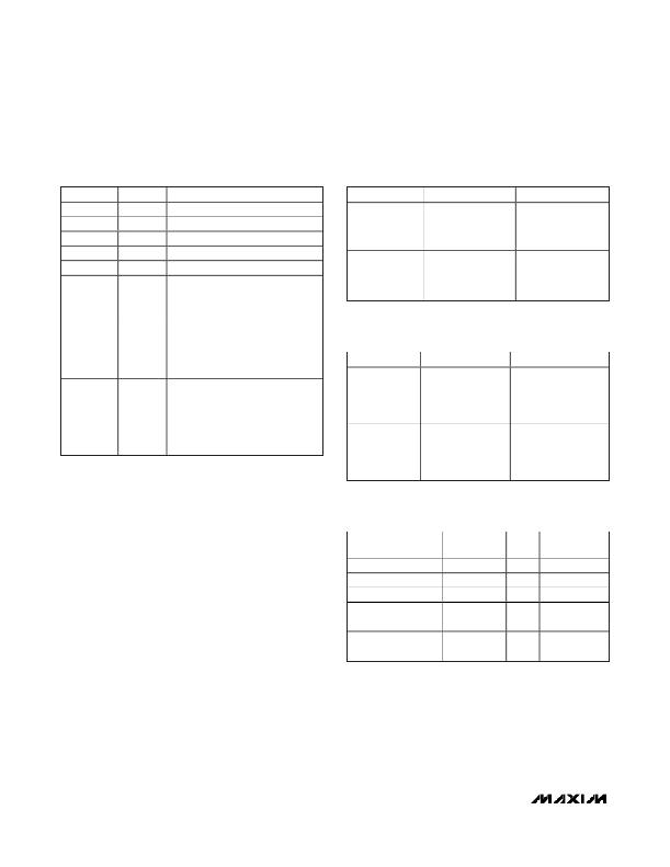
�Table� 11.� STAT2� Register�
�(Address� 0x2E)�
�Table� 12.� CHIP_ID1� Register�
�(Address:� 0x39)�
�BIT�
�NAME�
�DESCRIPTION�
�BIT�
�NAME�
�DESCRIPTION�
�B7� (MSB)�
�Reserved� for� future� use�
�B7� (MSB)�
�B6�
�B5�
�B4�
�B3�
�B2�
�OSDD�
�Reserved� for� future� use�
�Reserved� for� future� use�
�Reserved� for� future� use�
�Reserved� for� future� use�
�Open� Schottky� diode� detection�
�0� =� Schottky� diode� is� present�
�B6�
�B5�
�B4�
�B3�
�B2�
�B1�
�B0� (LSB)�
�DIE_TYPE[7:4]�
�DIE_TYPE[3:0]�
�BCD� character� 0�
�BCD� character� 7�
�1� =� Schottky� diode� is� missing�
�Thermal-shutdown� detection�
�0� =� No� thermal� shutdown� occurred�
�Table� 13.� CHIP_ID2� Register�
�(Address� 0x3A)�
�B1�
�TSD�
�1� =� MAX8831� has� entered� thermal�
�shutdown� since� the� last� read�
�operation� of� this� register�
�Output� overvoltage� detection�
�0� =� No� overvoltage� protection� has�
�BIT�
�B7� (MSB)�
�B6�
�B5�
�NAME�
�DASH� [7:4]�
�DESCRIPTION�
�BCD� character� 0�
�B0� (LSB)�
�OVP�
�occurred�
�1� =� MAX8831� has� entered� over�
�voltage� protection� since� last� read�
�B4�
�B3�
�operation� of� this� register�
�PCB� Layout�
�B2�
�B1�
�B0� (LSB)�
�MASK_REV� [3:0]�
�BCD� character� B�
�Due� to� fast� switching� waveforms� and� high� current�
�paths,� careful� PCB� layout� is� required.� Minimize� trace�
�lengths� between� the� IC� and� the� inductor,� the� diode,� the�
�input� capacitor,� and� the� output� capacitor.� Minimize�
�Table� 14.� Recommended� Inductors� for�
�the� MAX8831� Circuit�
�trace� lengths� between� the� input� and� output� capacitors�
�and� the� MAX8831� GND� terminal,� and� place� input� and�
�output� capacitor� grounds� as� close� together� as� possi-�
�ble.� Use� separate� power� ground� and� analog� ground�
�copper� areas,� and� connect� them� together� at� the� output�
�capacitor� ground.� Keep� traces� short,� direct,� and� wide.�
�Keep� noisy� traces,� such� as� the� LX� node� trace,� away�
�from� sensitive� analog� circuitry.� For� improved� thermal�
�performance,� maximize� the� copper� area� of� the� LX� and�
�PGND� traces.� Refer� to� the� MAX8831� EV� Kit� for� an�
�example� layout.�
�PART�
�TOKO� 1098AS-100M�
�TOKO� 1069AS-220M�
�FDK� MIP3226D100M�
�Coilcraft� EPL2014-�
�472ML�
�Coilcraft� DO2010-�
�472ML�
�L�
�(μH)�
�10�
�22�
�10�
�4.7�
�4.7�
�DCR�
�(m� Ω� )�
�290�
�570�
�160�
�231�
�800�
�I� SAT�
�(A)�
�0.75�
�0.47�
�0.9�
�650�
�650�
�SIZE� (mm)�
�2.8� x� 3.0� x� 1.2�
�3� x� 3� x� 1.8�
�3.2� x� 2.6� x� 1.0�
�2.0� x� 2.0� x� 1.45�
�2.0� x� 2.0� x� 1.0�
�24�
�______________________________________________________________________________________�
�发布紧急采购,3分钟左右您将得到回复。
相关PDF资料
MAX8834ZEWP+T
IC LED DRIVR BCKLGT FLASH 20-WLP
MAX8855EVKIT+
KIT EVAL FOR MAX8855
MAX8879ETG+T
IC LED DRVR WT/RGB BCKLGT 24TQFN
MAX8901BETA+TCH8
IC LED DRIVER WHITE BCKLGT 8TDFN
MAX8930EWJ+T
IC LED DRVR WT/RGB BCKLGT 49WLP
MAXQ2000-KIT
EVAL KIT FOR MAXQ2000
MAXQ610-KIT#
EVALUATION KIT FOR MAXQ610
MB2146-401-01A
KIT STARTER F2MC-8FX 3V
相关代理商/技术参数
MAX8833ETJ+
功能描述:直流/直流开关调节器 Dual 3A 2MHz Step-Down Regulator RoHS:否 制造商:International Rectifier 最大输入电压:21 V 开关频率:1.5 MHz 输出电压:0.5 V to 0.86 V 输出电流:4 A 输出端数量: 最大工作温度: 安装风格:SMD/SMT 封装 / 箱体:PQFN 4 x 5
MAX8833ETJ+T
功能描述:直流/直流开关调节器 Dual 3A 2MHz Step-Down Regulator RoHS:否 制造商:International Rectifier 最大输入电压:21 V 开关频率:1.5 MHz 输出电压:0.5 V to 0.86 V 输出电流:4 A 输出端数量: 最大工作温度: 安装风格:SMD/SMT 封装 / 箱体:PQFN 4 x 5
MAX8834YEVKIT+
功能描述:LED 照明开发工具 Adaptive Step-Up Converters with 1.5A Flash Driver RoHS:否 制造商:Fairchild Semiconductor 产品:Evaluation Kits 用于:FL7732 核心: 电源电压:120V 系列: 封装:
MAX8834YEWP+T
功能描述:LED照明驱动器 Adaptive Step-Up Converter RoHS:否 制造商:STMicroelectronics 输入电压:11.5 V to 23 V 工作频率: 最大电源电流:1.7 mA 输出电流: 最大工作温度: 安装风格:SMD/SMT 封装 / 箱体:SO-16N
MAX8834ZEWP+T
功能描述:LED照明驱动器 Adaptive Step-Up Converter RoHS:否 制造商:STMicroelectronics 输入电压:11.5 V to 23 V 工作频率: 最大电源电流:1.7 mA 输出电流: 最大工作温度: 安装风格:SMD/SMT 封装 / 箱体:SO-16N
MAX8836ZEREEE+T
功能描述:电流型 PWM 控制器 1.2A PWM Step-Down Converter RoHS:否 制造商:Texas Instruments 开关频率:27 KHz 上升时间: 下降时间: 工作电源电压:6 V to 15 V 工作电源电流:1.5 mA 输出端数量:1 最大工作温度:+ 105 C 安装风格:SMD/SMT 封装 / 箱体:TSSOP-14
MAX8836ZEWEEE+
制造商:Rochester Electronics LLC 功能描述: 制造商:Maxim Integrated Products 功能描述:
MAX8836ZEWEEE+T
制造商:Maxim Integrated Products 功能描述: